
Continuing from our first post, we assume here that the physical side of the Direct Connect has been configured, and we only need to complete the BGP configuration in order to exchange routes between AWS and on-premises devices.
Virtual Interface Types
Let’s begin by understanding the different Virtual Interface Types or VIFs that AWS references, as this will have an impact on your logical design as well as the routes that you will be expecting to receive.
A quick note; I have drawn the Direct Connect Gateway outside the AWS cloud for the sake of simplicity. The Direct Connect Gateway construct sits in the AWS Global backbone at the edge in the edge-POP.
The Public VIF propagates all AWS routes (which can be controlled using BGP communities) to the customer router. This can be useful for connecting to AWS public resources such as S3, DynamoDB, etc. or allowing you to terminate an IPSEC tunnel on a VGW endpoints public IP address.
The Private VIF allows you to connect directly to a particular VPC. In the above example, this could be a transit VPC and you could use third-party devices to manage the connections in the Cloud.
The Transit VIF allows you to associate a Transit Gateway with the Direct Connect Gateway. For most enterprise use cases this may be the most scalable way forward. This is also the VIF referred to in this blog post.
The Transit VIF can be used to extend the design across multiple Regions.
The Direct Connect Gateway is a Global construct and can be used to connect multiple regions.
In the above configuration traffic can flow from region to region via the Transit Gateway inter region peering.
Let’s make our design more robust/realistic. Here you may have multiple data centres connecting into the same Direct Connect gateway. This design is fine, but it should be noted that hairpinning data on the direct connect gateway is not currently supported.
The Direct Connect gateway does not allow for a redundant path between data centres.
However, adding a second Direct Connect gateway would allow using the Transit Gateway peering to be used for DC to DC traffic flows.
I personally don’t find this a good design. I believe that inter data center redundancy must be managed on the client side to avoid loss of transparency and incurring data charges unnecessarily.
Before moving on, let’s review some current limitations:
- Each Transit Gateway can only propagate 20 routes to the on-premises devices. This should be optimized using route summarization.
- Each Direct Connect Gateway can connect to max. 3 Transit Gateways, so design accordingly.
The Logical Design
I’m assuming a knowledge of BGP fundamentals here.
The above is the best book I have read on the subject.
I’ve simplified the diagram below by removing the physical intermediary infrastructure devices and concentrating on the logical endpoints.
Let’s review some key components:
- Direct Connect Gateway: Sits in the AWS global network and is a global construct – this is the device you will peer with
- Transit Gateway: Sits in the region and is a regional construct – It peers with the Direct Connect Gateway
Both the above “constructs” will have unique BGP AS numbers.
For example, when you configure the Transit Gateway you assign an ASN:
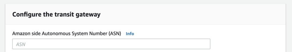
In our current example, the Transit Gateway has an ASN of 65020.
Transit Gateways should be defined and configured before the Direct Connect gateway, as you will need to associate these with the Direct Connect gateway.
The same is true when you configure the Direct Connect Gateway, which will serve as the BGP peer for your connection. You assign an AS number and configure the parameters of the device it will peer with (your BGP router).
Once you configure the Direct Connect Gateway, you can download a sample config for the BGP configuration on your end (depending on your device – I have seen Cisco and Juniper support).
Configure the BGP Peering
The part of the configuration that we will concern ourselves with here is between Cloud Edge 1 and the Direct Connect Gateway.
Once you have the downloaded config for your BGP router from the Direct Connect page on the AWS console, you can apply the configuration and verify that the BGP peering establishes correctly.
You will likely receive your AWS VPC routes immediately, however, you will have to add the on-premises networks that you wish to advertise to AWS to your BGP config.
Routing Propagation
Now that the peering session is configured, the routes will be propagated between AWS and the on-premises devices.
The prefixes that are to be advertised from AWS to the on-premises routers must be manually defined in the Direct Connect configuration in the AWS console. Currently, a maximum of 20 prefixes are allowed. Summarize appropriately.
Leave a comment below if there is any information missing here that you feel could be pertinent. I will then update the post as necessary.
Thanks for reading.